What is a Battery Management System (BMS)?
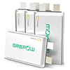
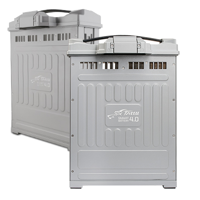
The power output depends on the battery, and the battery management system (BMS) is the core of it. It is a system for monitoring and managing the battery. It controls the charge and discharge of the battery by collecting and calculating parameters such as voltage, current, temperature, and SOC. The process, the management system that realizes the protection of the battery and improves the overall performance of the battery is an important link between the battery and the battery application equipment. The better BMS of foreign companies include UMC, Continental, Delphi, AVL, and FEV, etc. Now they basically follow the AUTOSAR architecture and ISO26262 functional safety requirements, with more software functions, higher reliability, and accuracy. Many domestic battery factories also have self-developed BMS products and applications, including Grepow battery manufacturer. With the rapid development of batteries and BMS technology, they have become one of the world's largest battery manufacturers. BMS mainly includes three parts: hardware, bottom layer software, and application layer software.
The hardware of the battery management system (BMS)
1. Architecture
The topology of Battery Management System(BMS) hardware is divided into two types: centralized and distributed.
(1) The centralized type
The centralized type is to concentrate all the electrical components into a large board, the sampling chip channel utilization is the highest and the daisy chain communication can be adopted between the sampling chip and the main chip, the circuit design is relatively simple, the product cost is greatly reduced, but All the collection wiring harnesses will be connected to the mainboard, which poses a greater challenge to the security of the BMS, and there may also be problems in the stability of the daisy chain communication. It is more suitable for occasions where the battery pack capacity is relatively small and the module and battery pack types are relatively fixed.
(2) The Distributed type
Distributed includes a mainboard and a slave board. It is possible that a battery module is equipped with a slave board. The disadvantage of this design is that if the number of battery modules is less than 12, the sampling channel will be wasted (generally there are 12 sampling chips. Channel), or 2-3 slave boards to collect all battery modules. This structure has multiple sampling chips in one slave board. The advantages are high channel utilization, cost-saving, flexibility in system configuration, and adaptation to different capacities. Modules and battery packs of different specifications and types.
2. Function
The hardware design and specific selection should be combined with the functional requirements of the vehicle and battery system. The general functions mainly include collection functions (such as voltage, current, and temperature collection), charging port detection (CC and CC2), and charging wake-up (CP and A+) ), relay control and status diagnosis, insulation detection, high voltage interlock, collision detection, CAN communication and data storage requirements.
(1) Main controller
Process the information reported from the controller and the high-voltage controller, and at the same time judge and control the battery operating status according to the reported information, realize the BMS-related control strategy, and make the corresponding fault diagnosis and processing.
(2) High voltage controller
Collect and report the total voltage and current information of the battery in real-time, and realize timely integration through its hardware circuit, and provide accurate data for the calculation of the state of charge (SOC) and the state of health (SOH) for the motherboard. Charge detection and insulation detection function.
(3) Slave controller
Real-time collection and reporting of battery cell voltage and temperature information, feedback of the SOH and SOC of each string of cells, and a passive equalization function, effectively ensuring the consistency of cells during power use.
(4) Sampling control harness
Provide hardware support for battery information collection and information interaction between controllers, and at the same time add redundant insurance function to each voltage sampling line, effectively avoid battery short circuit caused by wiring harness or management system.
3. Communication method
There are two ways to transfer information between the sampling chip and the main chip: CAN communication and daisy chain communication. CAN communication is the most stable. However, due to the high cost of power chips and isolation circuits, daisy chain communication is actually SPI communication. The cost is very low, and the stability is relatively poor. However, as the pressure on cost control is increasing, many manufacturers are shifting to the daisy chain mode. Generally, two or more daisy chains are used to enhance communication stability.
4. Structure
BMS(Battery Management System) hardware includes power supply IC, CPU, sampling IC, high-drive IC, other IC components, isolation transformer, RTC, EEPROM, CAN module, etc. The CPU is the core component, and the functions of different models are different, and the configuration of the AUTOSAR architecture is also different. Sampling IC manufacturers mainly include Linear Technology, Maxim, Texas Instruments, etc., including collecting cell voltage, module temperature, and peripheral configuration equalization circuits.
Bottom layer software
According to the AUTOSAR architecture, it is divided into many general functional modules, which reduces the dependence on hardware, and can realize the configuration of different hardware, while the application layer software changes little. The application layer and the bottom layer need to determine the RTE interface, and consider the flexibility of DEM (fault diagnosis event management), DCM (fault diagnosis communication management), FIM (function information management), and CAN communication reserved interfaces, which are configured by the application layer.
Application layer software of the BMS
The software architecture mainly includes high and low voltage management, charging management, state estimation, balance control, and fault management, etc.
1. High and low voltage management
Generally, when the power is on normally, the VCU will wake up the BMS through the hardwire or 12V of the CAN signal. After the BMS completes the self-check and enters the standby mode, the VCU sends the high-voltage command, and the BMS controls the closed relay to complete the high-voltage. When the power is off, the VCU sends a high-voltage command and then disconnects and wakes up 12V. It can be awakened by CP or A+ signal when the gun is plugged in in the power-off state.
2. Charging management
(1) Slow charge
Slow charging uses an AC charging station (or 220V power supply) to convert AC to DC to charge the battery through an on-board charger. The charging station specifications are generally 16A, 32A, and 64A, and it can also be charged through a household power supply. The BMS can be awakened by CC or CP signal, but it should be ensured that it can sleep normally after charging. The AC charging process is relatively simple, and it can be developed in accordance with the detailed regulations of the national standard.
(2) Fast charge
Fast charging is to charge the battery with DC output from the DC charging pile, which can achieve 1C or even higher rate charging. Generally, 80% of the power can be charged in 45 minutes. Wake up by the auxiliary power A+ signal of the charging pile, the fast charging process in the national standard is more complicated, and there are two versions of 2011 and 2015 at the same time, and the different understanding of the technical details of the charging pile manufacturer's unclear technical details of the national standard process also causes the vehicle charging adaptability A great challenge, so fast charging adaptability is a key indicator to measure the performance of BMS products.
3. Estimation function
(1) the State Of Power
SOP (State Of Power) mainly obtains the available charge and discharge power of the current battery through the temperature and SOC lookup table. The VCU determines how the current vehicle is used according to the transmitted power value. It is necessary to consider both the ability to release the battery and the protection of the battery performance, such as a partial power limit before reaching the cut-off voltage. Of course, this will have a certain impact on the driving experience of the whole vehicle.
(2) state of health
SOH (state of health) mainly characterizes the current state of health of the battery, which is a value between 0-100%. It is generally believed that the battery can no longer be used after it is lower than 80%. It can be expressed by the change of battery capacity or internal resistance. When using the capacity, the actual capacity of the current battery is estimated through the battery operating process data, and the ratio of the rated capacity to the rated capacity is the SOH. Accurate SOH will improve the estimation accuracy of other modules when the battery decays.
(3) the State Of Charge
SOC (State Of Charge) belongs to the BMS core control algorithm, which characterizes the current remaining capacity state, mainly through the ampere-hour integration method and EKF (Extended Kalman Filter) algorithm, combined with correction strategies (such as open-circuit voltage correction, full charge correction, charging End correction, capacity correction under different temperatures and SOH, etc.). The ampere-hour integration method is relatively reliable under the condition of ensuring the accuracy of current acquisition, but the robustness is not strong. Because of the error accumulation, it must be combined with a correction strategy. The EKF has strong robustness, but the algorithm is more complex and difficult to implement. Domestic mainstream manufacturers generally can achieve accuracy within 6% at room temperature, and it is difficult to estimate high and low temperatures and battery attenuation.
(4) the State Of Energy
SOE (State Of Energy) algorithm manufacturers do not develop much now or use a simpler algorithm, look up the table to get the ratio of the remaining energy to the maximum available energy in the current state. This function is mainly used to estimate the remaining cruising range.
4. Fault diagnosis
According to the different performance of the battery, it is divided into different fault levels, and in the case of different fault levels, the BMS and VCU will take different treatment measures, warning, limiting power, or directly cutting off the high voltage. Failures include data collection and rationality failures, electrical failures (sensors and actuators), communication failures, and battery status failures.
5. Balance control
The equalization function is to eliminate the inconsistency of the battery cells generated during battery use. According to the shortboard effect of the barrel, the cells with the worst performance during charging and discharging first reach the cut-off condition, and the other cells have some capabilities. It is not released, causing battery waste. Equalization includes active equalization and passive equalization. Active equalization is the transfer of energy from more monomers to fewer monomers, which will not cause energy loss, but the structure is complex, the cost is high, and the requirements for electrical components are relatively high. Relatively passive The balance structure is simple and the cost is much lower, but the energy will be dissipated and wasted in the form of heat. Generally, the maximum balance current is about 100mA. Now many manufacturers can achieve better balance effects using passive balance. The BMS(Battery Management System) control method, as the central control idea of the battery, directly affects the service life of the battery, the safe operation of the electric vehicle, and the performance of the entire vehicle. It has a significant impact on battery life and determines the future of new energy vehicles. A good battery management system will greatly promote the development of new energy vehicles.
If you are interested in the battery with BMS, please don't hesitate to contact us! Email: info@grepow.com Click here for more information on BMS: https://www.grepow.com/technology/bms.html
Related Articles
-
FPV Drone Types: All You Need to Know
2025-03-06 -
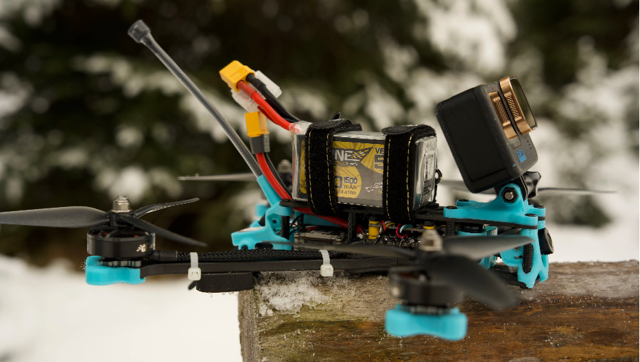
The Ultimate Guide to FPV Battey
2025-02-11 -
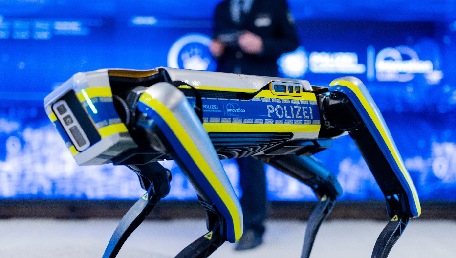
Exploring the Power Behind Quadrupedal Robots: A Deep Dive into Robot Dog Batteries
2025-01-22
Related products
-
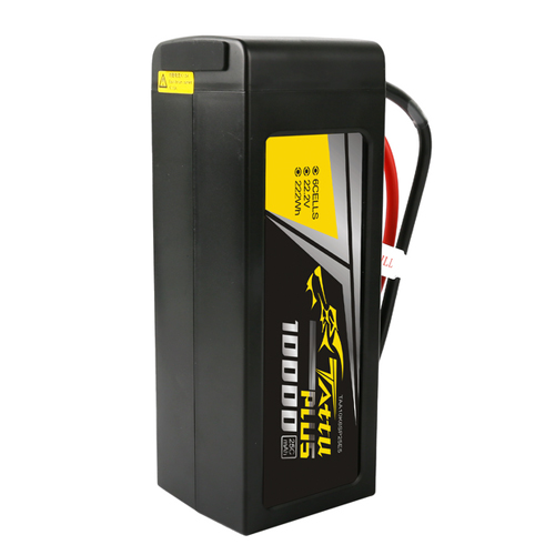
Tattu Plus 6S 10000mAh 22.2V 25C Lipo Smart Drone Battery
-
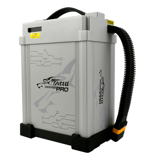
Tattu Pro 14S Lipo 22000mAh 51.8V Smart UAV Drone Battery Pack
-
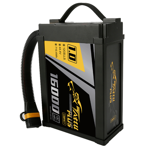
Tattu Plus 1.0 Compact 12S 16000mAh 44.4V 15C Lipo Smart Drone Battery


