Low Temperature Intelligent Lithium Battery Management System Design
This paper introduces a design scheme of a low-temperature intelligent lithium battery management system, which manages 32-cell single-cell batteries with 20Ah 4 strings and 8 pairs. The solution has basic protection, power metering, charge balancing, and fault logging. The experiment verified that the functions of the system were good and met the design requirements. Most of the current battery management systems are designed for large-capacity battery packs and short-lived time applications. The power consumption of such management systems is large, the cycle time of the battery is short, and the power consumption of the management system itself is not low.
Used on low power instrumentation fields. A gas remote monitoring instrument, the average system current is only a few milliamperes and requires continuous operation for more than 6 months at low temperature. In order to meet the application of this project, this paper presents a design solution for a low-temperature intelligent lithium battery management system, which manages 32 20Ah cells in 4 strings of 8 pairs of single cells. Basic protection, power metering, charge balancing, and fault logging. The experiment verified that the functions of the system were good and met the design requirements.
1. The overall structure of the system
The low-temperature lithium battery management system is mainly composed of basic protection circuit, fuel gauge, equalization circuit, secondary protection, etc., as shown in Figure 1. Based on low power consumption considerations, many low-power devices are used in the design. For example, the processor uses MSP430FG439 low-power single-chip microcomputer; the voltage reference adopts REF3325, the power consumption of the reference power supply is extremely low only 3.9μA; the operational current of the operational amplifier The LT1495 is the only 1.5μA; the digital potentiometer uses the AD5165 with quiescent current as low as 50nA. Power management circuits are added to intermittent operating circuits with large operating currents to reduce energy consumption. The rated voltage of the low-temperature battery pack is 14.8V, which is formed by connecting four groups of batteries. Each group of batteries contains 8 single cells, and the normal working voltage is 2.5~4.2V.

Each group collects the voltage of each group of cells, and the processor issues an instruction to the protection execution circuit according to the voltage level to perform corresponding protection actions. The equalization circuit is realized by a single-chip microcomputer and a triode, instead of the equalization dedicated chip. The system records the maximum value of voltage and current, the time the battery has been used, the amount of remaining power, and other anomaly information in the storage device. The processor provides a TTL communication interface, and the on-site computer can read the logs in the storage device through a TTLRS232 conversion module. Protection failure occurs during the charging process in order to prevent an abnormality such as an MCU crash. A secondary protection circuit is added. If the voltage exceeds the preset value, the secondary protection circuit will be activated to blow the three-terminal fuse to prevent the accident.
2. Hardware design
Protection Execution Circuit
The protection execution circuit is the actuator for the protection action, CH is the charge control switch, and DISCH is the discharge control switch. The corresponding protection action is performed by controlling CH and DISCH. The circuit diagram is shown in Fig. 2. CH and DISCH are asserted low during normal operation, and both M1 and M2 are turned on. When a discharge overcurrent or over-discharge occurs, DISCH is set to a high level. At this time, Q2 is turned off and Q3 is turned on, and the charge of the M2 gate capacitor is quickly discharged so that M2 can be turned off instantaneously to complete the protection. When charging overcurrent or overcharge occurs, set CH high and turn off M1. The MOSFET in the circuit uses the IRF4310, which has an on-resistance of only 7kΩ and a current capability of 140A.
If you are interested in our products, please don’t hesitate to contact us at any time! Email: info@grepow.com Grepow Website: https://www.grepow.com/
Related Articles
-
The Ultimate Guide to Grepow Jump Starter
2025-03-27 -

How to Choose Lithium Batteries for Cold Weather?
2024-09-19 -

Next-Generation eVTOL Battery Technology
2024-08-22
Related products
-
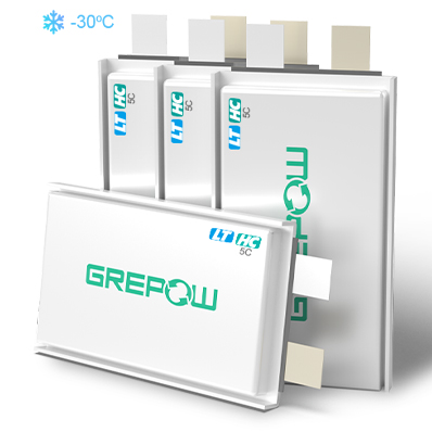
-30℃ 5C Low-Temperature High Discharge Battery
-
-40℃ Low Temperature LiFePO4 Battery
-
-40℃ to 60℃ Low Temperature Lipo Battery

